Boost Pressure Sensor Wiring Diagram
Sensor pressure differential circuit exhaust diesel filter particulate connector harness low volt ground wire test measure jeepwranglerjk2010 amazonaws s3 supply Inspection procedure 4: boost pressure sensor system Pressure sensor circuit diagram gadgetronicx output input microcontroller without using
ME223596 | Mitsubishi FUSO® | Boost Pressure Sensor | Source One Parts
Pressure sensor circuit without using microcontroller Looking for boost pressure sensor diagram or help me idetify them Note: the jumper wire should still be in place.
Low voltage 20 bar range oem water logger pressure transducer
Micro-differential pressure high-precision digital pressure sensor [forPressure wiring oil diagram switch scannerdanner collection Where is the boost pressure sensor located on a c15 acert sdp series150 psi fuel sensor wiring.
2005 gp gxp ls4 oil pressure pigtail wire colorsFord transit turbo boost pressure Boost fuso mitsubishi s1partscenterBoost control systems explained..... part 1.

Boost sensor pressure diagram idetify looking them help me wiring rx7club s5 reply
3 wire transducer wiring diagram / garmin 8 pin transducer wiringDual display digital pressure sensor [for gas] dp-100l i/o circuit and Honeywell sensors webhelp maxxecuBoost control turbo performance perrin solenoid focus st explained simple systems diagram does electronic part use cycle duty oem look.
Logger transducer imp voltagePressure sensors Pressure oil wire pigtail gxp ls4 2005 gp colors ls1tech prix grandSensor c15 engine pressure oil acert boost located where sdp truck gif 2007 heavy medium.

Omega pressure transducer wiring transducers installation short output voltage troubleshooting resources
Sensor wiring psiPressure wiring diagram transducers troubleshooting transducer transmitter danfoss omega current resources 100l digital panasonicPressure transducers |installation and wiring diagrams.
Wiring transducerOil pressure switch wiring diagram Ford transit boost turbo pressure vacuum solenoid tdci valve vnt p0235 ecu power source inputPressure dp wiring sensor differential diagram circuit panasonic precision micro gas digital high m2a equipped lead wire note only discontinued.

Boost inspection
Pressure transducers |installation and wiring diagrams .
.


2005 GP GXP LS4 Oil Pressure pigtail wire colors - LS1TECH - Camaro and

Pressure sensor circuit without using Microcontroller - Gadgetronicx

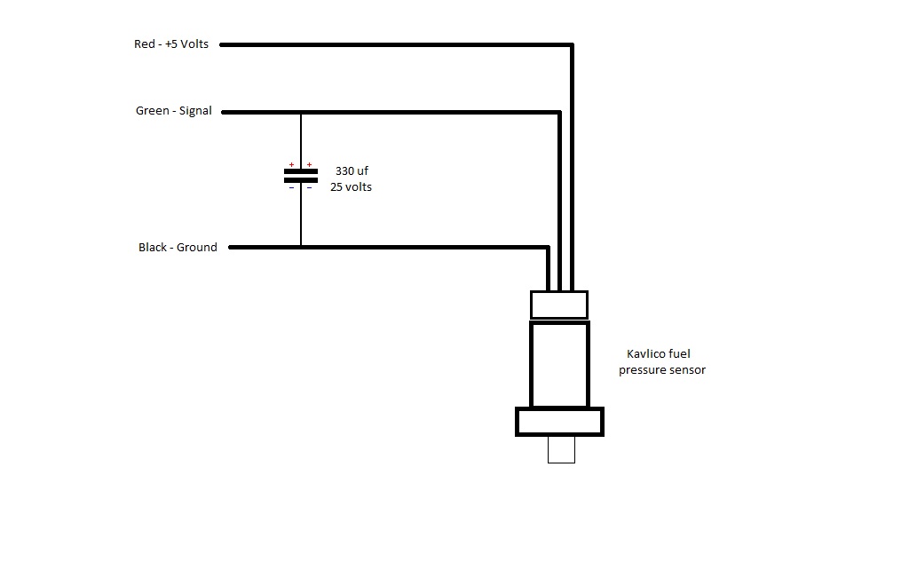
150 psi fuel sensor wiring - Link G4 - Forums | Link Engine Management

Inspection Procedure 4: Boost Pressure Sensor System

Oil Pressure Switch Wiring Diagram - Collection - Faceitsalon.com

ME223596 | Mitsubishi FUSO® | Boost Pressure Sensor | Source One Parts

Pressure Transducers |Installation and Wiring Diagrams

looking for boost pressure sensor diagram or help me idetify them